Configuring Rosemount Level Gauges with Radar Master program
Setting up the level gauge is quite a diligent task. There are many types of level gauges, as well as their manufacturers. There are various programs to set up level gauges, as well as ways to connect them to a laptop. Each instrument comes with instruction for setting up. It is difficult to set up the device correctly using only the setup instructions. On this page, I propose to consider the setting up of Rosemount5300 level gauge including phase separation. How to connect to an instrument with PACTware program can be viewed on the page «Instrument settings with PACTware». On this page we will consider the option of connecting a level gauge with the Foundation fieldbus communication protocol.
1. How to install the Radar Master program.
It is impossible to download the Radar Master program for adjusting the level gauges for free. This program is provided on a CD together with the level gauge. Optionally, you can buy the program on a website of a developer. I don’t know exactly how much it costs. To get information, it is necessary to send a request by filling in your details. When installing the program using HART protocol, you shall have the driver installed on your existing modem. Information on installation the driver on HART modem can be found on the page “Setting up devices with PACTware”. There are no problems when installing Radar Master program. To connect via FOUNDATION fieldbus (hereinafter FF), you shall have a USB Fieldbus Modem. For instance, the manufacturer Emerson.
The modem is supplied with the software. Detailed instructions for installing the program and connecting to the device are available in the operating manual.
2. How to connect to the instrument through Foundation fieldbus protocol
In the operating manual for FF modem there is a drawing of connecting a laptop to the instrument.

This diagram is also applicable when connecting to the instrument in a laboratory condition. The proposed field connection diagram assumes connecting the instrument to a laptop in the field, that is not always possible. According to safety requirements, a laptop shall be explosion-proof when used in a hazardous area. It is not always convenient to carry a laptop in the field, especially in bad weather conditions or in sub-zero temperatures. When setting up the instrument, the laptop battery power may turn off, and «an error» can occur. Instrument readings will be lost. Since usually a very short period of time is given to configure the instrument by operating team, then a long-term absence of readings may lead to a disruption of the technological process. To be able to set up the instrument and monitor its operation for a long time, FF modem is connected in a marshaling cabinet. Before performing any actions with any instrument using FF protocol, as usual, it is necessary to coordinate all your activities with the operating team. The instrument shall be put into «service mode». i.e. Instrument Engineer shall switch program to «Out of Service» mode.
When connecting to the instrument in operating mode, a software failure may occur, and the readings of all the instruments of one «FF segment» may be lost («went down»).

In the marshaling cabinet it is necessary to find the segment fieldbus wires to which the instrument is connected. In parallel, FF modem shall be connected. «Polarity» does not make sense for FF protocol. Then, Radar Master program is launched.
To connect to the level gauge, when starting the program, select the type of Foundation fieldbus communication protocol.

The program starts. The level gauge configuration window opens. Then, we search for instrument. The list of instruments connected to the program will be displayed in the «List of instruments» window.

We choose the necessary instrument. Connect it

Then go to the «General Settings» menu. Check whether the instrument is switched to «Out of Service» mode or not. If the block is in «Auto» mode, we switch to «Out of Service» mode.
3. Check and save the level gauge settings.
By pressing the button «Read», we can see the instrument settings.

Save the instrument configuration in a separate folder.

Launch the instrument setup wizard. Using «Forward» button, we view and save all the necessary instrument settings for us.

Enter to the tank setup menu. Read them. Save the data. Usually I save all settings as screenshots in a separate folder created for the level gauge.

In this sheet there is a menu «Operating conditions». It is necessary to check that the range of the dielectric capacity of the medium is correctly set.
4.Types of tanks
The most difficult is to set up the parameters of the tank. For proper adjustment, it is necessary to measure in correct manner the tank base height, the liquid level, the level of the phase separation. For sure, these measurements are not carried out by instrumentation specialists. Usually, it is done by technological personnel, in compliance with all safety requirements. To be sure that the measurements are correct, most often you need to be present personally when measuring. In commercial metering, the level in the tank is measured after the oil has settled for at least two hours from the filling end. There are different types of tanks.
- РВС/TVS — vertical stainless steel tank with fixed roof w/t pontoon;
- РВСП/TVSP — vertical stainless steel tank with fixed roof and pontoon;
- РВСПК/TVSPR — vertical stainless steel tank with floating roof;
You can see detailed design of tanks in GOST 31385-2016 «VERTICAL CYLINDRICAL STEEL TANKS FOR OIL AND PETROLEUM PRODUCTS». We need data that must be put in the level gauge. The technology for level measuring in tanks is also different. Consider the option of measuring the level in a steel cylindrical tank with a water/oil product phase separation.

5. How to measure the level and phase separation in the tank with an electronic measure tape
It is possible to measure the level and phase separation level in the tank, using an electronic measure tape — for example, «HERMetic Gtex 2000»

An electronic measure tape is used to measure the level in tanks, without contact of the worker with the medium. The measure tape has a quick-detachable connection with a conduit mounted on the measuring flange. When carrying out measurements, all precautions of the operating instructions must be observed. Before taking measurements, the tape shall be grounded.
After connecting to the flange, the ball valve opens and measurement is done. Upon contact with the liquid surface, the sound signal emitted by measure tape changes to shorter signals. When the measure tape electrodes reach the phase separation level, the sound signal changes to an intermittent one.
Read in more detail the procedure for measuring with a tape in the operating instructions via the link.
When measuring with an electronic measure tape, consider length of all mounting structures up to the base tank height. Before measurement start, with the tape completely reeled on the spool, the reading of the measure tape will already be 474 mm.

To this amount it is necessary to add the value equal to Ln from the counter measuring flange of the tape to the base height of the tank (usually this is the edge of the gauge hatch flange). The sum of two values will be Lnr value. This value is subtracted from the tape value to D1 level in the tank and to D2 phase separation level.

We get 2 values. D1 is the distance from the base height to the level in the tank. D2 is the distance from the base height to the level of the phase separation. Subtracting these values from the base height Lb, we obtain the values of the liquid level in the tank L1 and the level of the phase separation L2. Information of the base height is provided in the tank passport.
It very rarely happens that the flange of the gauge hatch and the flange on where the level gauge is placed are on the same level. For each pipe on the tank, the passport indicates the difference in height between the base height Lb and the height of the location of the level gauge nozzle d1 and d2.
By adding d1 and d2 values to the tank base height, we obtain the base height values for each level gauge.
All that remains is to correctly enter all the values in the level gauges corresponding to the measurements. As a result of calculations, the level gauges shall show the real values of the level inside the tank. In this case, the difference in readings between the level gauges shall coincide with the difference of the measured values with measure tape between the level in the tank L1 and the phase separation L2. This value is also displayed on the operator’s console.

It is very convenient to carry out measurements with an electronic measure tape. But sometimes it is not possible to take measurements with it. Photo below shows you that the measure tape electrodes located in the lower part of the gauge are filled up with oil products. At the same time, it is impossible to determine phase separation. In this case, you have to use a conventional mechanical measuring gauge.

6. Carrying out measurements of the level in the tank with a mechanical measure tape.
When measuring level and phase separation in a tank using a conventional tape, measurements have to be done in a different way.
Measuring gauge also allows to determine the phase separation in the tank. This requires a water-sensitive indicator paste for oil products. A water-sensitive paste is applied to the part of steel strip where the phase separation level is supposed to be located. The length of the section with applied paste can be either 1 or 2 meters. The water-sensitive paste is applied with a thin layer (0.2 ¸0.3) mm on the surface of gauge in strips from two opposite sides.
In the gauge hatches of the tanks, there is a special guide groove for the steel tape. The tape shall be lowered and raised along this guide groove. The gauge shall be lowered very carefully to the tank bottom. In this case, the tape measurements shall match the base height in the tank passport. In case of deviation from the reference data of the base height, it should be understood that there are bottom sediments in the tank. The difference between the nameplate value and the measured value will be the sediment level. With different values of the tank base height, it is necessary to focus on the distance from the tank base height to the level of oil products and the level of phase separation. In the absence of bottom sediments, the level and phase separation can be measured using a direct method.

Raise the tape straight up, without shifting to the side, to avoid distorting the wetting line on the tape. On the tape, after the appearance of wetted part, the height of the liquid level in the tank or the distance to the level of oil products from the base height is determined.
With the further rise of measure tape, it is necessary to determine the phase separation level. The water-sensitive paste applied to the tape will change its color at the level of oil / water phase separation. Determine the water level in the tank, or the distance to the level of phase separation from the base height.The level measurement in the tank is carried out twice. If the measurement results differ by 1 mm, then their average value is taken as the measurement result. If the obtained discrepancy of measurements is more than 1 mm, the measurements are repeated twice more and the average of the three closest measurements is taken.
When taking measurements, it is necessary to comply with safety requirements.
7. Entering the measured level values into Radar Master program
All that remains is to correctly enter the measured readings into the tank data in the Radar Master program of the level gauge.

The operating manual for the level gauge describes everything in detail. When setting up a level gauge, the setup instructions should be at hand. Or, as a minimum, you should read it at least once.
8. Determination of the level inside the tank by level gauge reflected signal.
After entering the data into the level gauge settings using Radar Master software, sometimes the readings of the level gauge may not correspond to the measured data. In this case, it will be necessary to find out the reason for the deviation of the level gauge readings.
Consider the example of the produced water tank given above.
When measuring the tank innage level, the readings of the level gauge coincide with the value measured with a tape. The level gauge readings of phase separation do not correspond to the measured value. To find out the reason, it is necessary to go to «Echo Signal» menu. The signal curve is displayed in this menu.

In order to adjust the level gauge, it is necessary to understand what the echo signal curve is. Let me try to explain it very simple. A signal from transmitter is sent through the waveguide or through the air (depending on the transmitter). This signal is reflected from all obstacles on the way. The main parameter of the curve tracing is the medium dielectric capacitivity. Depending on the change in the medium dielectric capacitivity, the magnitude of the reflected signal also changes. As a result, we get an echo signal curve with different amplitudes. The level gauge program calculates the level in the tank, depending on the data entered into the level gauge and on the reflected echo signal. This program is developed by each manufacturer. Therefore, different manufacturers may have different parameters that need to be entered into the setup program. But the principle of echo curve reflection is practically the same for all manufacturers and for different transmitters.
Once you understand what is reflected on the echo curve, you can imagine what is happening inside the tank. The signal originates from the Upper Reference Point. The first obstacle for the echo, for sure, will be the flange itself and connection of transducer with probe. The magnitude of the signal reflected from the flange and connections is large. The obstacle for measurement is also created by the pipe itself, where the level gauge is mounted. Therefore , the signal reflected from the flange is cut off programmatically — Distance Offset. This signal is no longer considered when calculating the level. This is followed by a reflected signal from the liquid surface. Its amplitude is the largest. Since the medium is non-homogeneous during the transition from the oil layer to the water layer, several different reflected interferences can be seen on the echo curve. But in the area of the transition of oil phase into water phase, there will be the highest reflected signal — the Phase Separation. Further, various interference signals are displayed on the echo curve. This can be interference from the measured medium — inhomogeneity of the liquid filled into the tank, various adhesions to the probe. It can also be interference caused by the measuring probe itself. This may be damage to the cable probe, jumpers on a double rigid or coaxial probe, etc.

To understand the type of interference by the probe itself, it is necessary to dismantle the level gauge, rinse it well, and clean the waveguide. When connected to a level gauge with the Radar Master software, all waveguide interference signals can be seen. Below is the echo curve of a clean wire waveguide with a length of 12350 mm. There are interferences. The interference signal does not exceed 500 mV. But these interferences indicate that the wire waveguide is damaged. In places of damage, various deposits can accumulate. These can be both oil products and various salt deposits.

The interference signal can rise significantly and the level gauge will falsify the readings. Therefore, the waveguides must be handled very carefully, to avoid any damage.
9. Possible reasons for incorrect readings of the level gauge.
Sometimes there are situations when the interference signal by the measured medium is much larger than the phase separation signal. Consider this example.
Two level gauges are installed on the tank. The first level gauge measures the innage level. Level gauge without a phase separation measurement function. It works perfectly. Its readings coincide with the level measured by the tape.

The second level gauge with the function of measuring the phase separation is installed on the same tank.

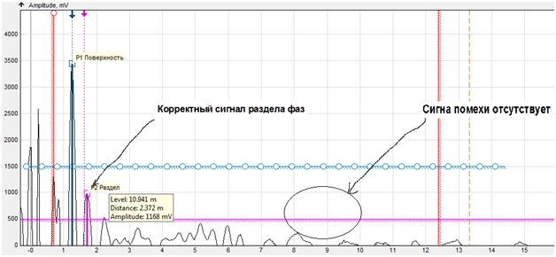
The phase separation level readings do not coincide with the measured value. According to the measurements, the level of water/oil phase separation is located in the area of distance D2 about 5.5 meters. In the interval of 9… 10 meters, there is a large interference signal. The same interference signal can be seen on the first level gauge. It was not possible to cut off this interference signal by any methods recommended in the instructions for setting up the level gauge. It was also impossible to understand whether this interference was from the tank internal structures. There was no passport for this tank.
This level gauge was temporarily mounted on the flange of the measuring pipe.
There is no interference signal on the echo curve. The phase separation level is also shown correctly. It was decided to mount the level gauge on the measuring pipe. The issue of incorrect reading of the phase separation level has been resolved.
Oftentimes, a violation of the process by operating team leads to incorrect readings of the level gauge. For example, phase separation in a tank where there should be no phase separation.
For instance, a tank for collecting sulfuric acid. A non-contact level gauge is used. In case of violation of the process parameters, alkylate enters the tank. The phase separation appears. In principle, there is no any sense for the level gauge. It should show the overall level. But the more alkylate on the surface of sulfuric acid, the lower level is shown in the tank by level gauge. No attempts to adjust the correctness of the level gauge readings have yielded results. The manufacturer’s recommendation was to replace the level gauge with another one with a phase separation function. Since no one will buy a new level gauge, the operating team had to comply with the process parameters. The level gauge began to work correctly.
The configuration of the level gauges working with the PACTware program is performed similarly. The connection of level meters by the PACTware program is described on the page «Setting up devices by the PACTware program«.
Chat in the forum. Share your experience on how problems with level gauges were solved.

